NucleoTNC PCB
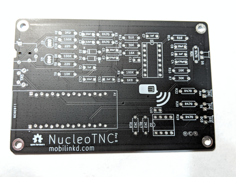
This is a bare PCB for the Nucleo TNC breadboard project.
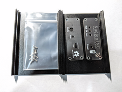
We also sell a metal enclosure that will fit the PCB.
Please note that since mid-2021, the supply of Nucleo32-L432KC modules has been in extreme short supply. Make sure you can source this part. There are no viable alternatives for this component.
This PCB uses almost all of the same components as the breadboard project. The design goal was to allow experimenters to take their breadboard project and give it a more permanent home on a real printed circuit board.
Most of the component values are printed on the board for easy assembly. Two 100nF capacitors do not have values on the silkscreen.
There are a few small component differences.
The PCB requires a different 3.5mm jack. You will need a CUI SJ-43515TS or SJ-43514 jack when building the PCB in place of the Sparkfun breadboard module. (Be sure you get the through-hole version, not the surface mount one -- with the exact same part number.)
There are also a few optional components that make mounting the PCB in an enclosure more convenient: a power indicator LED, an auxiliary LED, and a reset button. There are spots for two additional capacitors for decoupling of the power plane, a 10uF and a 1uF. These are not required.
The reset button is a C&K PTS645VL58-2 LFS. The additional LEDs are blue and yellow, respectively and each requires a additional 470 Ohm resistor. Make sure the blue LED has a voltage drop below 3.3V.
The PCB will come with spacers designed to sit between the PCB and the Nucleo32 board. This raises the Nucleo32 up from the PC, limiting how far the pins from the Nucleo32 board stick through the other side. The spacers are required in order to fit in the optional enclosure.
This is the new Rev C board. The primary changes from the Rev B board are layout changes and new footprints for the MOSFETs and a couple of capacitors to make soldering the project a bit easier. There are a couple of capacitor value changes to improve low-frequency response, and an additional diode on the PTT circuit.
The Rev B board had a fixes from Rev A. The power LED will line up properly with the case panel. C1 was changed to 1uF to improve low-frequency response. The Mobilinkd logo on the board has been fixed. And the pins for the Nucleo32 have been staggered to provide a press-fit for the Nucleo32 board. The Nucleo32 can be inserted into the PCB and should work without being soldered in. (There are no guarantees that this will work, and it will likely only work for a few insertions.)


